آردوینو Micro
| 
|
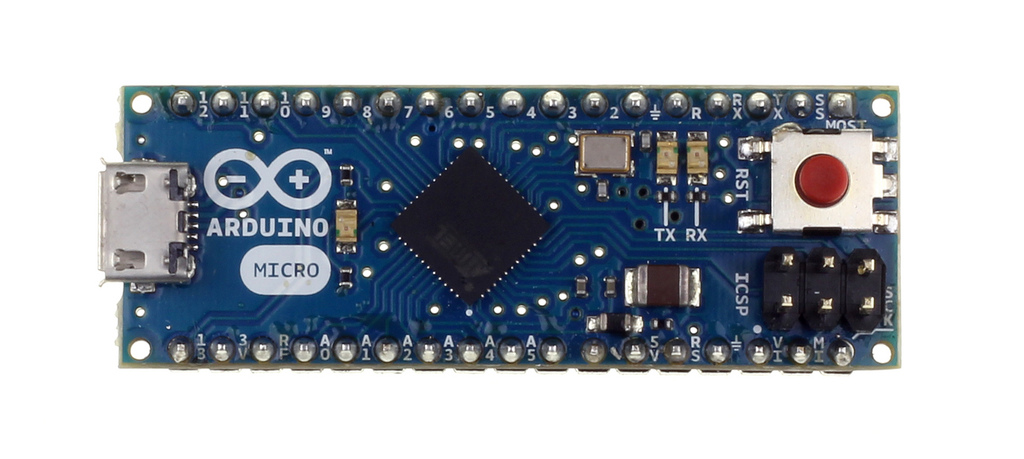
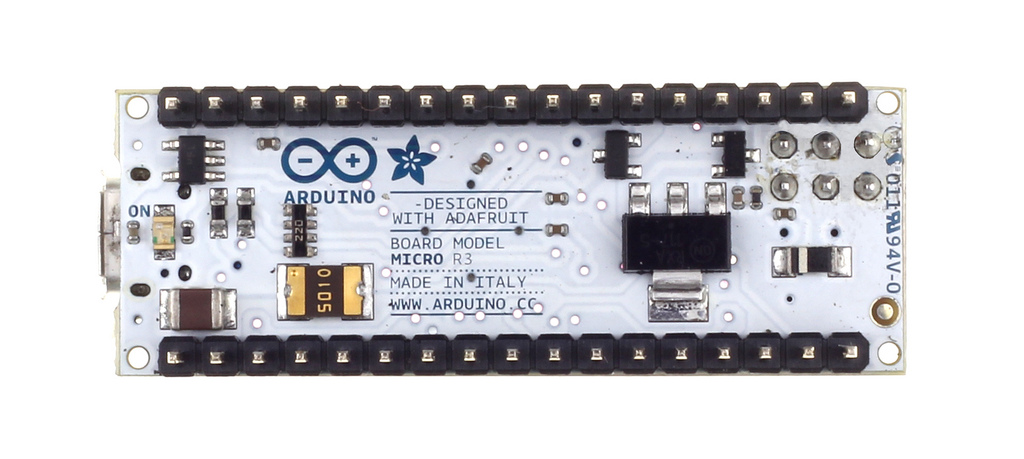
| آردوینو Micro نمای مقابل | آردوینو Micro نمای پشت |
 |
 |
معرفی
آردوینو مدل Micro یک برد میکروکنترلر بر پایه ATmega32u4 می باشد (datasheet) که با مشارکت Adafruit ایجاد شده است. این برد دارای 20 پین دیجیتال ورودی/خروجی (که7 تای آن می تواند به عنوان خروجی PWM و 12 تای آن می تواند به عنوان ورودی آنالوگ استفاده شود)، یک نوسان ساز (oscillator) کریستال 16 مگاهرتزی، یک اتصال USB میکرو، یک ICSP header، و یک دکمه ریست است. این برد همچنین شامل هر چیزی ست که جهت پشتیبانی میکروکنترلر مورد نیاز است؛ برای شروع، به سادگی با یک کابل USB میکرو، برد را به یک کامپیوتر متصل کنید. طراحی فیزیکی آن به گونه ای است که موجب می شود به سادگی روی یک بردبورد سوار شود.
آردوینو Micro شبیه به آردوینو Leonardo می باشد؛ به این معنی که میکروکنترلر ATmega32u4 دارای یک ارتباط USB آماده است، که نیاز به یک پردازنده جانبی را برطرف می کند. این مسئله آردوینو Micro را قادر می سازد تا برای کامپیوتری که به آن متصل است، علاوه بر اینکه یک پورت مجازی serial/Com(CDC) است، نقش یک ماوس یا صفحه کلید را ایفا کند. این برد پیامدهای دیگری نیز برای رفتار برد دارد؛ در صفحه راهنمای آغاز کار جزئیاتی در این زمینه موجود است.
خلاصه
| میکروکنترلر | ATmega32u4 |
| ولتاژ عملیاتی | 5 ولت |
| ولتاژ ورودی (پیشنهادی) | 12-7 ولت |
| ولتاژ ورودی (محدوده) | 20-6 ولت |
| پین های دیجیتال ورودی/خروجی | 20 |
| کانال های PWM | 7 |
| کانال های ورودی آنالوگ | 12 |
| جریان DC روی هر پین ورودی/خروجی | 40 میلی آمپر |
| جریان DC جهت پین 3.3 ولت | 50 میلی آمپر |
| حافظه فلش | 32 کیلوبایت (ATmega32u4) که 4 کیلوبایت آن توسط bootloader استفاده شده است. |
| SRAM | 2.5 کیلوبایت (ATmega32u4) |
| EEPROM | 1 کیلوبایت (ATmega32u4) |
| سرعت ساعت | 16 مگاهرتز |
شماتیک و طرح مرجع
EAGLE files: arduino-micro-reference-design.zip
Schematic: arduino-micro-schematic-rev3b.pdf
Power
The Arduino Micro can be powered via the micro USB connection or with an external power supply. The power source is selected automatically.
External (non-USB) power can come either from a DC power supply or battery. Leads from a battery or DC power supply can be connected to the Gnd and Vin pins.
The board can operate on an external supply of 6 to 20 volts. If supplied with less than 7V, however, the 5V pin may supply less than five volts and the board may be unstable. If using more than 12V, the voltage regulator may overheat and damage the board. The recommended range is 7 to 12 volts.
The power pins are as follows:
- VI. The input voltage to the Arduino board when it's using an external power source (as opposed to 5 volts from the USB connection or other regulated power source). You can supply voltage through this pin.
- 5V. The regulated power supply used to power the microcontroller and other components on the board. This can come either from VIN via an on-board regulator, or be supplied by USB or another regulated 5V supply.
- 3V. A 3.3 volt supply generated by the on-board regulator. Maximum current draw is 50 mA.
- ⏚ Ground pins.
Memory
The ATmega32u4 has 32 KB (with 4 KB used for the bootloader). It also has 2.5 KB of SRAM and 1 KB of EEPROM (which can be read and written with the EEPROM library).
Input and Output
Each of the 20 digital i/o pins on the Micro can be used as an input or output, using pinMode(), digitalWrite(), and digitalRead() functions. They operate at 5 volts. Each pin can provide or receive a maximum of 40 mA and has an internal pull-up resistor (disconnected by default) of 20-50 kOhms. In addition, some pins have specialized functions:
- Serial: 0 (RX) and 1 (TX). Used to receive (RX) and transmit (TX) TTL serial data using the ATmega32U4 hardware serial capability. Note that on the Micro, the Serial class refers to USB (CDC) communication; for TTL serial on pins 0 and 1, use the Serial1 class.
- TWI: 2 (SDA) and 3 (SCL). Support TWI communication using the Wire library.
- External Interrupts: 0(RX), 1(TX), 2 and 3. These pins can be configured to trigger an interrupt on a low value, a rising or falling edge, or a change in value. See the attachInterrupt() function for details.
- PWM: 3, 5, 6, 9, 10, 11 and 13. Provide 8-bit PWM output with the analogWrite() function.
- SPI: on the ICSP header. These pins support SPI communication using the SPI library. Note that the SPI pins are not connected to any of the digital I/O pins as they are on the Arduino Uno, they are only available on the ICSP connector and on the nearby pins labelled MISO, MOSI and SCK.
- RX_LED/SS This is an additional pin with respect to the Leonardo. It is connected to the RX_LED that indicates the activity of transmission during USB communication, but is can also used as slave select pin (SS) in SPI communication.
- LED: 13. There is a built-in LED connected to digital pin 13. When the pin is HIGH value, the LED is on, when the pin is LOW, it's off.
- Analog Inputs: A0-A5, A6 - A11 (on digital pins 4, 6, 8, 9, 10, and 12). The Micro has a total of 12 analog inputs, pins from A0 to A5 are labelled directly on the pins and the other ones that you can access in code using the constants from A6 trough A11 are shared respectively on digital pins 4, 6, 8, 9, 10, and 12. All of which can also be used as digital I/O. Each analog input provide 10 bits of resolution (i.e. 1024 different values). By default the analog inputs measure from ground to 5 volts, though is it possible to change the upper end of their range using the AREF pin and the analogReference() function.
There are a couple of other pins on the board:
- AREF. Reference voltage for the analog inputs. Used with analogReference().
- Reset. Bring this line LOW to reset the microcontroller. Typically used to add a reset button to shields which block the one on the board.
Pinout
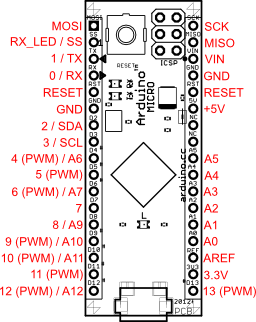
Pin Mapping of the Arduino Micro displays the complete functioning for all the pins, to use them as in the Leonardo.
See also the mapping between Arduino pins and ATmega32u4 ports.
Communication
The Micro has a number of facilities for communicating with a computer, another Arduino, or other microcontrollers. The ATmega32U4 provides UART TTL (5V) serial communication, which is available on digital pins 0 (RX) and 1 (TX). The 32U4 also allows for serial (CDC) communication over USB and appears as a virtual com port to software on the computer. The chip also acts as a full speed USB 2.0 device, using standard USB COM drivers. On Windows, a .inf file is required. The Arduino software includes a serial monitor which allows simple textual data to be sent to and from the Arduino board. The RX and TX LEDs on the board will flash when data is being transmitted via the USB connection to the computer (but not for serial communication on pins 0 and 1).
A SoftwareSerial library allows for serial communication on any of the Micro's digital pins.
The ATmega32U4 also supports I2C (TWI) and SPI communication. The Arduino software includes a Wire library to simplify use of the I2C bus; see the documentation for details. For SPI communication, use the SPI library.
The Micro appears as a generic keyboard and mouse, and can be programmed to control these input devices using the Keyboard and Mouse classes.
Programming
The Micro can be programmed with the Arduino software (download). Select "Arduino Micro from the Tools > Board menu. For details, see the reference and tutorials.
The ATmega32U4 on the Arduino Micro comes pre-burned with a bootloader that allows you to upload new code to it without the use of an external hardware programmer. It communicates using the AVR109 protocol.
You can also bypass the bootloader and program the microcontroller through the ICSP (In-Circuit Serial Programming) header; see these instructions for details.
Automatic (Software) Reset and Bootloader Initiation
Rather than requiring a physical press of the reset button before an upload, the Micro is designed in a way that allows it to be reset by software running on a connected computer. The reset is triggered when the Micro's virtual (CDC) serial / COM port is opened at 1200 baud and then closed. When this happens, the processor will reset, breaking the USB connection to the computer (meaning that the virtual serial / COM port will disappear). After the processor resets, the bootloader starts, remaining active for about 8 seconds. The bootloader can also be initiated by pressing the reset button on the Micro. Note that when the board first powers up, it will jump straight to the user sketch, if present, rather than initiating the bootloader.
Because of the way the Micro handles reset it's best to let the Arduino software try to initiate the reset before uploading, especially if you are in the habit of pressing the reset button before uploading on other boards. If the software can't reset the board you can always start the bootloader by pressing the reset button on the board.
USB Overcurrent Protection
The Micro has a resettable polyfuse that protects your computer's USB ports from shorts and overcurrent. Although most computers provide their own internal protection, the fuse provides an extra layer of protection. If more than 500 mA is applied to the USB port, the fuse will automatically break the connection until the short or overload is removed.
Physical Characteristics
The maximum length and width of the Micro PCB are 4.8cm and 1.77cm respectively, with the USB connector extending beyond the former dimension. The layout allows for easy placement on a solderless breadboard..