آردوینو Due
|
|
||
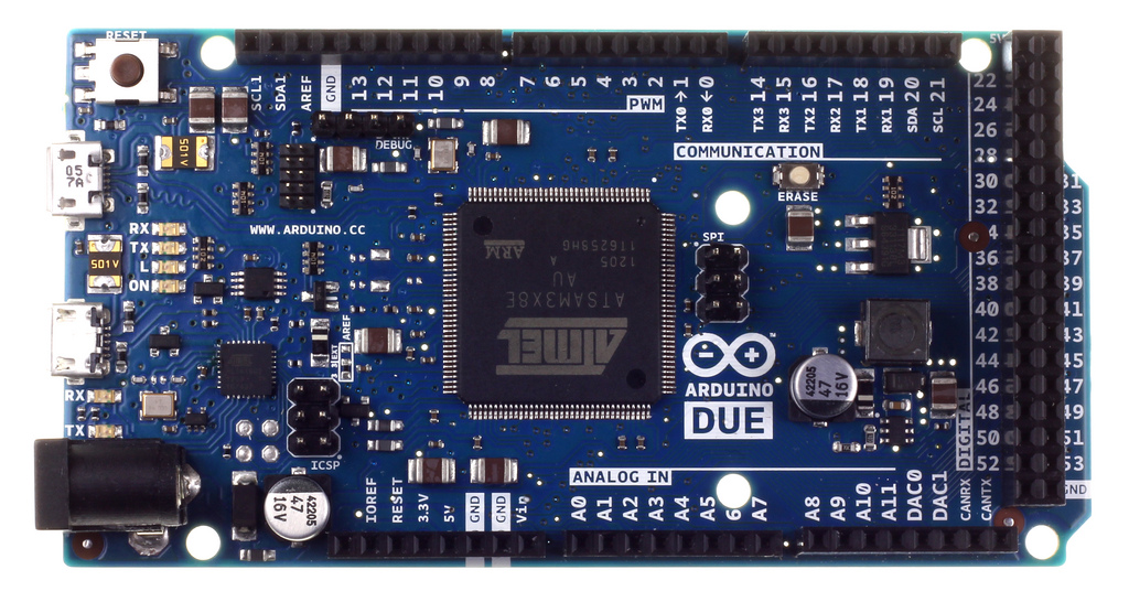
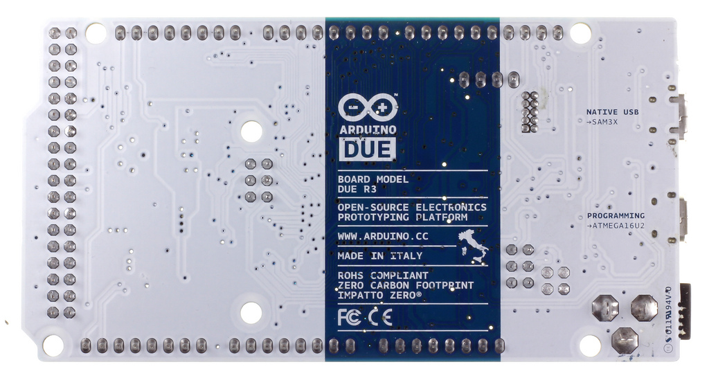
| آردوینو Due نمای مقابل | آردوینو Due نمای پشت |

|

|
معرفی
برد آردوینو Due یک میکروکنترلر بر پایه SAM3X8E ARM Cortex-M3 CPU از شرکت Atmel می باشد.(datasheet). این برد، اولین برد آردوینویی است که بر اساس میکروکنترلر با هسته ARM 32 بیتی پایه ریزی شده است. دارای 54 پین دیجیتال ورودی/خروجی (که 12 تای آن می تواند به عنوان خروجی PWM استفاده شود)، 12 ورودی آنالوگ، 4 پورت UARTs (پورت های سریال سخت افزاری)، و یک ساعت 84 مگاهرتزی، an USB OTG capable connection ، یک DAC (دیجیتال به آنالوگ)، 2 عدد TWI، یک پاور جک، یک SPI header، یک JTACG header، یک دکمه ریست و یک دکمه پاک کردن می باشد.
هشدار: بر خلاف دیگر بردهای آردوینو، برد آردوینو Due با ولتاژ 3.3 ولت کار می کند. حداکثر ولتاژی که پین های ورودی/خروجی می توانند تحمل کنند همین 3.3 ولت است. اعمال ولتاژ های بالاتر همچون 5ولت به یک پین ورودی/خروجی، می تواند به برد آسیب بزند.
این برد، هرچیزی را که جهت پشتیبانی از میکروکنترلر مورد نیاز است، شامل می شود؛ برای آغاز کار، برد را با یک کابل micro-USB به سادگی به کامپیوتر متصل کنید و یا با یک آداپتور AC-to-DC یا باتری، به آن ولتاژ بدهید. برد Due با همه شیلدهای آردوینو که با 3.3ولت کار می کنند، و همچنین با 1.0 Arduino pinout سازگار است.
برد Due از 1.0 pinout پیروی می کند:
- TWI: پین های SDA و SCL که در نزدیکی پین AREF قرار دارند.
- پین IOREF که اجازه می دهد یک شیلد را با پیکربندی مناسب جهت تطبیق با ولتاژی که توسط برد فراهم شده است، متصل کنید. این قابلیت، به شیلدها امکان می دهد تا با برد 3.3 ولتی همچون Due و بردهای AVR-based که با ولتاژ 5 ولت کار می کنند، خود را تطبیق دهند.
- یک پین که متصل نیست و جهت کاربردهای آتی در نظر گرفته شده است.
برد Due یک انجمن اختصاصی جهت بحث پیرامون برد دارد.
مزایای هسته ARM
برد Due یک هسته ARM 32 بیتی دارد که می تواند بر بردهای میکروکنترلر 8بیتی غالب شود. برجسته ترین تفاوتهای آنها عبارتند از:
- یک هسته 32 بیتی، که عملیات را روی داده های 4 بایتی درون یک کلاک PUی تکی فراهم می کند. (جهت کسب اطلاعات بیشتر، صفحه نوع Int را مطالعه کنید).
- کلاک CPU با فرکانس 84 مگاهرتز.
- 96 کیلوبایت حافظه SRAM.
- 512 کیلوبایت حافظه فلش برای کد.
- یک کنترلر DMA که می تواند جهت انجام وظایف فشرده، به CPU کمک کند.
شماتیک، طرح مرجع و نقشه پین
EAGLE files: arduino-Due-reference-design.zip
Schematic: arduino-Due-schematic.pdf
Pin Mapping: SAM3X Pin Mapping page
خلاصه
| میکروکنترلر | AT91SAM3X8E | |
| ولتاژ عملیاتی | 3.3 ولت | |
| ولتاژ ورودی (پیشنهادی) | 7-12 ولت | |
| ولتاژ ورودی (محدوده) | 6-16 ولت | |
| پین های دیجیتال ورودی/خروجی | 54 (12 تای آن خروجی PWM تولید می کنند.) | |
| پین های ورودی آنالوگ | 12 | |
| پین های خروجی آنالوگ | 2 (DAC) | |
| کل جریان خروجی DC روی تمام خطوط ورودی/خروجی | 130 میلی آمپر | |
| جریان DC جهت پین 3.3 ولت | 800 میلی آمپر | |
| جریان DC جهت پین 5 ولت | 800 میلی آمپر | |
| حافظه فلش | 512 کیلوبایت جهت برنامه های کاربر موجود است. | |
| SRAM | 96 کیلوبایت (دو عدد بانک : 64 کیلوبایت و 32 کیلوبایت) | |
| سرعت ساعت | 84 مگاهرتز |
Power
The Arduino Due can be powered via the USB connector or with an external power supply. The power source is selected automatically.
External (non-USB) power can come either from an AC-to-DC adapter (wall-wart) or battery. The adapter can be connected by plugging a 2.1mm center-positive plug into the board's power jack. Leads from a battery can be inserted in the Gnd and Vin pin headers of the POWER connector.
The board can operate on an external supply of 6 to 20 volts. If supplied with less than 7V, however, the 5V pin may supply less than five volts and the board may be unstable. If using more than 12V, the voltage regulator may overheat and damage the board. The recommended range is 7 to 12 volts.
The power pins are as follows:
- VIN. The input voltage to the Arduino board when it's using an external power source (as opposed to 5 volts from the USB connection or other regulated power source). You can supply voltage through this pin, or if supplying voltage via the power jack, access it through this pin.
- 5V. This pin outputs a regulated 5V from the regulator on the board. The board can be supplied with power either from the DC power jack (7 - 12V), the USB connector (5V), or the VIN pin of the board (7-12V). Supplying voltage via the 5V or 3.3V pins bypasses the regulator, and can damage your board. We don't advise it.
- 3.3V. A 3.3 volt supply generated by the on-board regulator. Maximum current draw is 800 mA. This regulator also provides the power supply to the SAM3X microcontroller.
- GND. Ground pins.
- IOREF. This pin on the Arduino board provides the voltage reference with which the microcontroller operates. A properly configured shield can read the IOREF pin voltage and select the appropriate power source or enable voltage translators on the outputs for working with the 5V or 3.3V.
Memory
The SAM3X has 512 KB (2 blocks of 256 KB) of flash memory for storing code. The bootloader is preburned in factory from Atmel and is stored in a dedicated ROM memory. The available SRAM is 96 KB in two contiguous bank of 64 KB and 32 KB. All the available memory (Flash, RAM and ROM) can be accessed directly as a flat addressing space.
It is possible to erase the Flash memory of the SAM3X with the onboard erase button. This will remove the currently loaded sketch from the MCU. To erase, press and hold the Erase button for a few seconds while the board is powered.
Input and Output
- Digital I/O: pins from 0 to 53
Each of the 54 digital pins on the Due can be used as an input or output, using pinMode(), digitalWrite(), and digitalRead() functions. They operate at 3.3 volts. Each pin can provide (source) a current of 3 mA or 15 mA, depending on the pin, or receive (sink) a current of 6 mA or 9 mA, depending on the pin. They also have an internal pull-up resistor (disconnected by default) of 100 KOhm. In addition, some pins have specialized functions: - Serial: 0 (RX) and 1 (TX)
- Serial 1: 19 (RX) and 18 (TX)
- Serial 2: 17 (RX) and 16 (TX)
- Serial 3: 15 (RX) and 14 (TX)
Used to receive (RX) and transmit (TX) TTL serial data (with 3.3 V level). Pins 0 and 1 are connected to the corresponding pins of the ATmega16U2 USB-to-TTL Serial chip. - PWM: Pins 2 to 13
Provide 8-bit PWM output with the analogWrite() function. the resolution of the PWM can be changed with the analogWriteResolution() function. - SPI: SPI header (ICSP header on other Arduino boards)
These pins support SPI communication using the SPI library. The SPI pins are broken out on the central 6-pin header, which is physically compatible with the Uno, Leonardo and Mega2560. The SPI header can be used only to communicate with other SPI devices, not for programming the SAM3X with the In-Circuit-Serial-Programming technique. The SPI of the Due has also advanced features that can be used with the Extended SPI methods for Due. - CAN: CANRX and CANTX
These pins support the CAN communication protocol but are not not yet supported by Arduino APIs. - "L" LED: 13
There is a built-in LED connected to digital pin 13. When the pin is HIGH, the LED is on, when the pin is LOW, it's off. It is also possible to dim the LED because the digital pin 13 is also a PWM outuput. - TWI 1: 20 (SDA) and 21 (SCL)
- TWI 2: SDA1 and
SCL1.
Support TWI communication using the Wire library. - Analog Inputs: pins from A0 to A11
The Due has 12 analog inputs, each of which can provide 12 bits of resolution (i.e. 4096 different values). By default, the resolution of the readings is set at 10 bits, for compatibility with other Arduino boards. It is possible to change the resolution of the ADC with analogReadResolution(). The Due’s analog inputs pins measure from ground to a maximum value of 3.3V. Applying more then 3.3V on the Due’s pins will damage the SAM3X chip. The analogReference() function is ignored on the Due.
The AREF pin is connected to the SAM3X analog reference pin through a resistor bridge. To use the AREF pin, resistor BR1 must be desoldered from the PCB.
- DAC1 and DAC2
These pins provides true analog outputs with 12-bits resolution (4096 levels) with the analogWrite() function. These pins can be used to create an audio output using the Audio library.
Other pins on the board:
- AREF
Reference voltage for the analog inputs. Used with analogReference(). - Reset
Bring this line LOW to reset the microcontroller. Typically used to add a reset button to shields which block the one on the board.
Communication
The Arduino Due has a number of facilities for communicating with a computer, another Arduino or other microcontrollers, and different devices like phones, tablets, cameras and so on. The SAM3X provides one hardware UART and three hardware USARTs for TTL (3.3V) serial communication.
The Programming port is connected to an ATmega16U2, which provides a virtual COM port to software on a connected computer (To recognize the device, Windows machines will need a .inf file, but OSX and Linux machines will recognize the board as a COM port automatically.). The 16U2 is also connected to the SAM3X hardware UART. Serial on pins RX0 and TX0 provides Serial-to-USB communication for programming the board through the ATmega16U2 microcontroller. The Arduino software includes a serial monitor which allows simple textual data to be sent to and from the board. The RX and TX LEDs on the board will flash when data is being transmitted via the ATmega16U2 chip and USB connection to the computer (but not for serial communication on pins 0 and 1).
The Native USB port is connected to the SAM3X. It allows for serial (CDC) communication over USB. This provides a serial connection to the Serial Monitor or other applications on your computer. It also enables the Due to emulate a USB mouse or keyboard to an attached computer. To use these features, see the Mouse and Keyboard library reference pages.
The Native USB port can also act as a USB host for connected peripherals such as mice, keyboards, and smartphones. To use these features, see the USBHost reference pages.
The SAM3X also supports TWI and SPI communication. The Arduino software includes a Wire library to simplify use of the TWI bus; see the documentation for details. For SPI communication, use the SPI library.
Programming
The Arduino Due can be programmed with the Arduino software (download). For details, see the reference and tutorials.
Uploading sketches to the SAM3X is different than the AVR microcontrollers found in other Arduino boards because the flash memory needs to be erased before being re-programmed. Upload to the chip is managed by ROM on the SAM3X, which is run only when the chip's flash memory is empty.
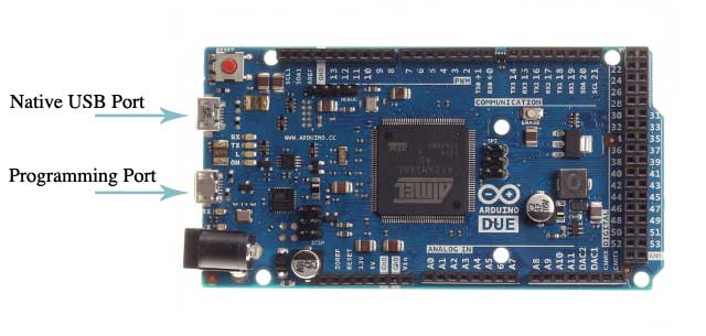
Either of the USB ports can be used for programming the board, though it is recommended to use the Programming port due to the way the erasing of the chip is handled :
- Programming port: To use this port, select "Arduino Due (Programming Port)" as your board in the Arduino IDE. Connect the Due's programming port (the one closest to the DC power jack) to your computer. The programming port uses the 16U2 as a USB-to-serial chip connected to the first UART of the SAM3X (RX0 and TX0). The 16U2 has two pins connected to the Reset and Erase pins of the SAM3X. Opening and closing the Programming port connected at 1200bps triggers a “hard erase” procedure of the SAM3X chip, activating the Erase and Reset pins on the SAM3X before communicating with the UART. This is the recommended port for programming the Due. It is more reliable than the "soft erase" that occurs on the Native port, and it should work even if the main MCU has crashed.
- Native port: To use this port, select "Arduino Due (Native USB Port)" as your board in the Arduino IDE. The Native USB port is connected directly to the SAM3X. Connect the Due's Native USB port (the one closest to the reset button) to your computer. Opening and closing the Native port at 1200bps triggers a 'soft erase' procedure: the flash memory is erased and the board is restarted with the bootloader. If the MCU crashed for some reason it is likely that the soft erase procedure won't work as this procedure happens entirely in software on the SAM3X. Opening and closing the native port at a different baudrate will not reset the SAM3X.
Unlike other Arduino boards which use avrdude for uploading, the Due relies on bossac.
The ATmega16U2 firmware source code is available in the Arduino repository. You can use the ISP header with an external programmer (overwriting the DFU bootloader). See this user-contributed tutorial for more information.
USB Overcurrent Protection
The Arduino Due has a resettable polyfuse that protects your computer's USB ports from shorts and overcurrent. Although most computers provide their own internal protection, the fuse provides an extra layer of protection. If more than 500 mA is applied to the USB port, the fuse will automatically break the connection until the short or overload is removed.
Physical Characteristics and Shield Compatibility
The maximum length and width of the Arduino Due PCB are 4 and 2.1 inches respectively, with the USB connectors and power jack extending beyond the former dimension. Three screw holes allow the board to be attached to a surface or case. Note that the distance between digital pins 7 and 8 is 160 mil (0.16"), not an even multiple of the 100 mil spacing of the other pins.
The Arduino Due is designed to be compatible with most shields designed for the Uno, Diecimila or Duemilanove. Digital pins 0 to 13 (and the adjacent AREF and GND pins), analog inputs 0 to 5, the power header, and "ICSP" (SPI) header are all in equivalent locations. Further the main UART (serial port) is located on the same pins (0 and 1). Please note that I2C is not located on the same pins on the Due (20 and 21) as the Duemilanove / Diecimila (analog inputs 4 and 5).